| Stock Items Ship The Same Day. | Quick Delivery for Non-Stock Items. | Email us for a Quote. |
| Phone: 973-706-8475 | Email: Contact Us |
Directional Couplers
| Features | Applications |
|---|---|
| Octave and multioctave designs up to 40 Ghz | Sampling incident and reflected power levels |
| Low mainline loss | Line monitoring power level |
| High directivity | Power measurement |
| Stripline designs | PCS, GSM, LTE, 5G |
For a specific application consult sales office at E-MAIL
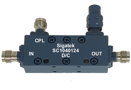
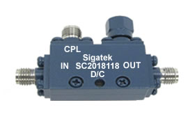
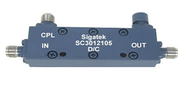
Microwave Wideband RF Coaxial Directional Couplers, 6 dB, 10 dB, 20 dB, 30 dB
Broadband, Octave and Multioctave band RF Couplers SMA, 2.92mm, 2.4mm, 1.85mm
Directional Couplers 6dB, 10 dB, 20 dB, 30 dB 0.5-18 Ghz, 1-40 Ghz, 2-40 Ghz
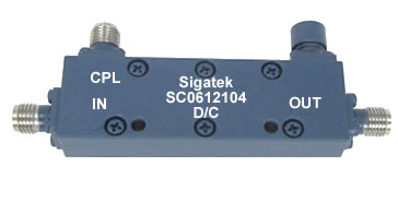
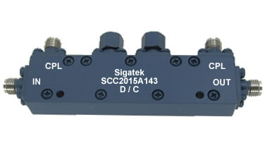
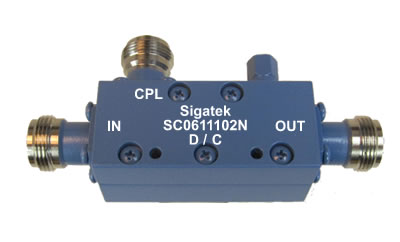
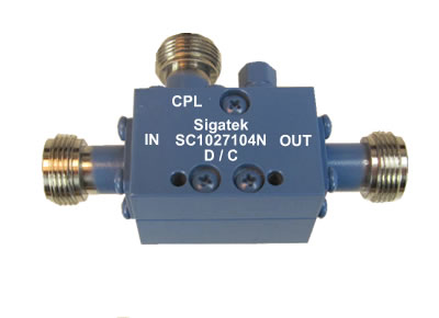
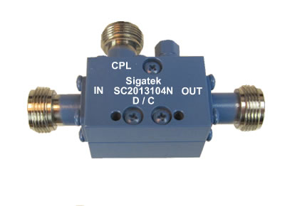
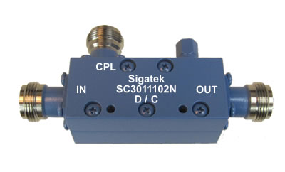
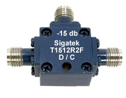
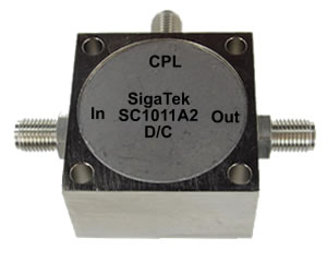
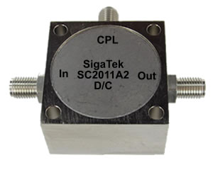
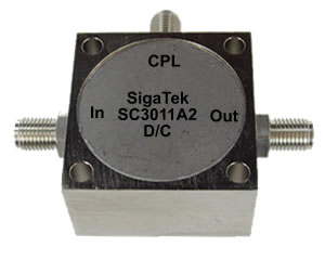
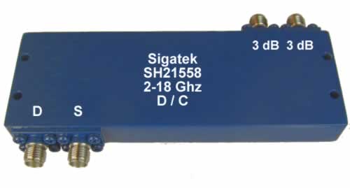
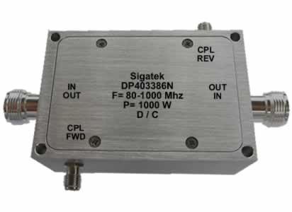
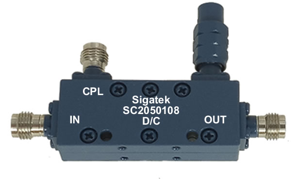
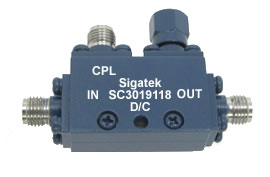
SigaTek offers a wide range of Microwave RF directional couplers 6 dB 10 dB 20 dB and 30 dB covering the frequency range of 500 Mhz to 40 Ghz. All directional couplers are designed using stripline techniques and with specifications that exceed commercial applications. Microwave Directional couplers are used in a wide range of applications. Sampling incident and reflected power levels, line monitoring power level, power measurement, instrumentation power monitoring, RF test equipments, receivers and transmitters. Directional RF couplers are used to sample energy from the transmission line where this energy is fed to a detector and then to a signal processing equipment. Return loss measurement is another application that couplers are used. This application is done better with the use of high directivity dual couplers (two couplers connected back to back).
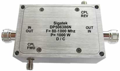
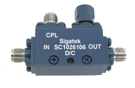
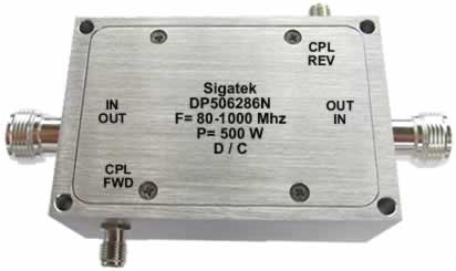
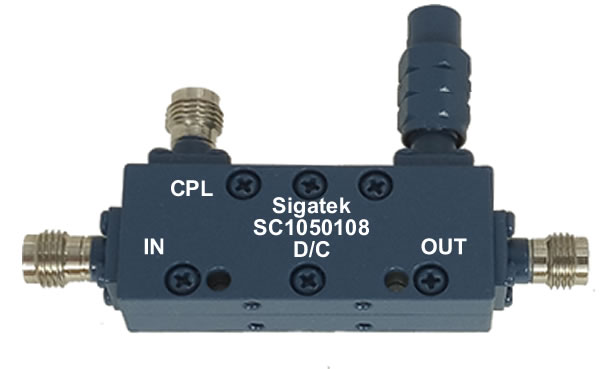
Microwave Octave Band Couplers |
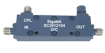
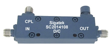
Microwave Multi-Octave Band Couplers |
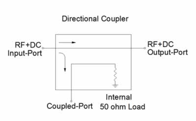
Schematic of an Octave Band Coupler |
|---|---|---|
 |
 |
 |
| Theoretical Insertion Loss Due to Coupling factor (dB) | |||||||
|---|---|---|---|---|---|---|---|
| Coupling (dB) | 3 | 6 | 10 | 20 | 30 | 40 | 50 |
| Coupling Loss (dB) | 3.01 | 1.2560 | 0.4560 | 0.0436 | 0.0043 | 0.0004 | 0.00004 |
Directional Couplers Definition of Specifications
Coupling
The ratio in dB of the incident power fed into the Input port to the Coupled port power with all unsused ports terminated to matched 50 ohms. Due to wide frequencies band the Nominal coupling is defined as the arithmetic mean-average of the maximum and the minimum coupling within the frequency band. Wikipedia Mean Average Definition.
Coupling Tolerance
The specified allowable unit to unit variation in dB in nominal coupling.
Coupling Flatness
The maximum peak to peak variation in dB from the nominal coupling over the specified frequency range.
Coupling Theoretical Loss
The theoretical main line loss in dB due to power coupled to the coupling port.
Insertion Loss
The physical loss of the device from input to output in the specified frequency range. The total loss is the sum of the coupling theretical loss and the insertion loss.
Directivity
The power ratio in dB of the RF power from the mainline to the coupled port in the forward direction compared to that in the reverse direction. Is the same as the Isolation which is the power ratio from the output to the coupling port with all unused ports terminated to matched 50 ohms.
VSWR-Return Loss
The voltage standing wave ratio specified for each port when all unused ports are terminated to matched 50 ohms.
Average Power
The continous wave CW average power handling capability of the device. Due a variety of designs, dielectric materials and interconnect assemblies Sigatek's devices are rated with different power specifications. See specific data sheet for the specified power rating.
New Products For February - Directional Couplers

